Compaction force
Can crushing was treated as a buckling-driven problem, then checked against experimental and commercial compaction data.
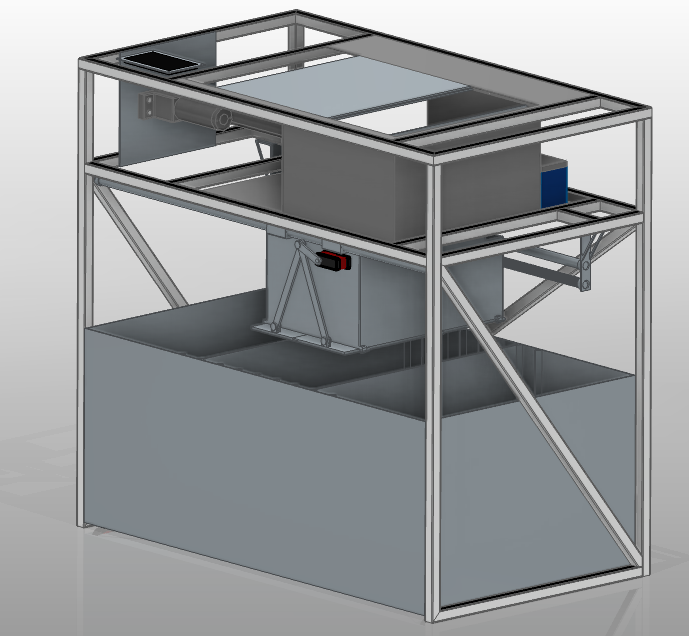
This project focused on developing a compact domestic waste compactor for paper, plastic and cans through a requirement-driven mechanical design workflow: market and requirement analysis, functional decomposition, concept generation, CAD architecture, component sizing, FEM validation and topology-oriented refinement.
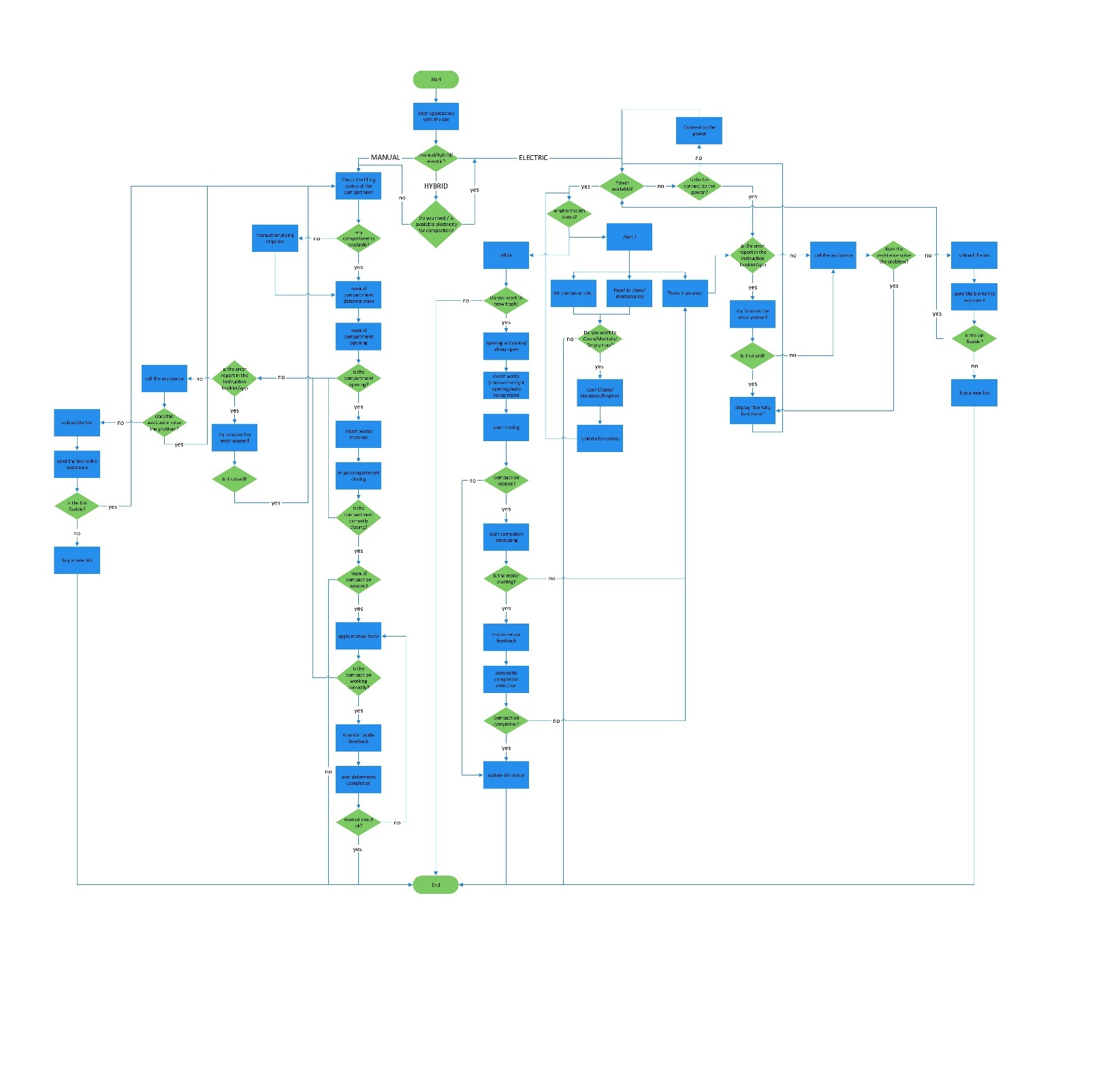
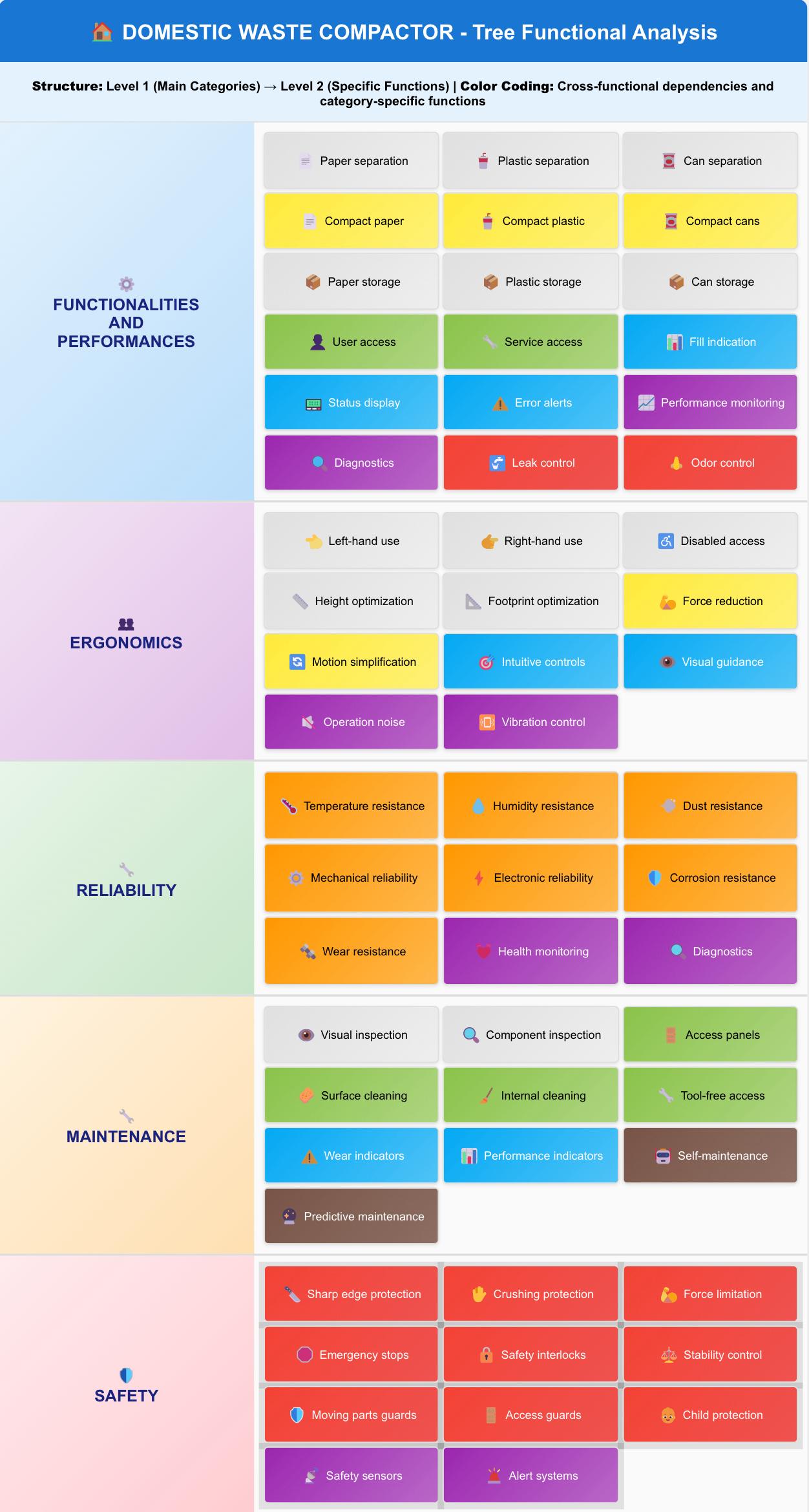
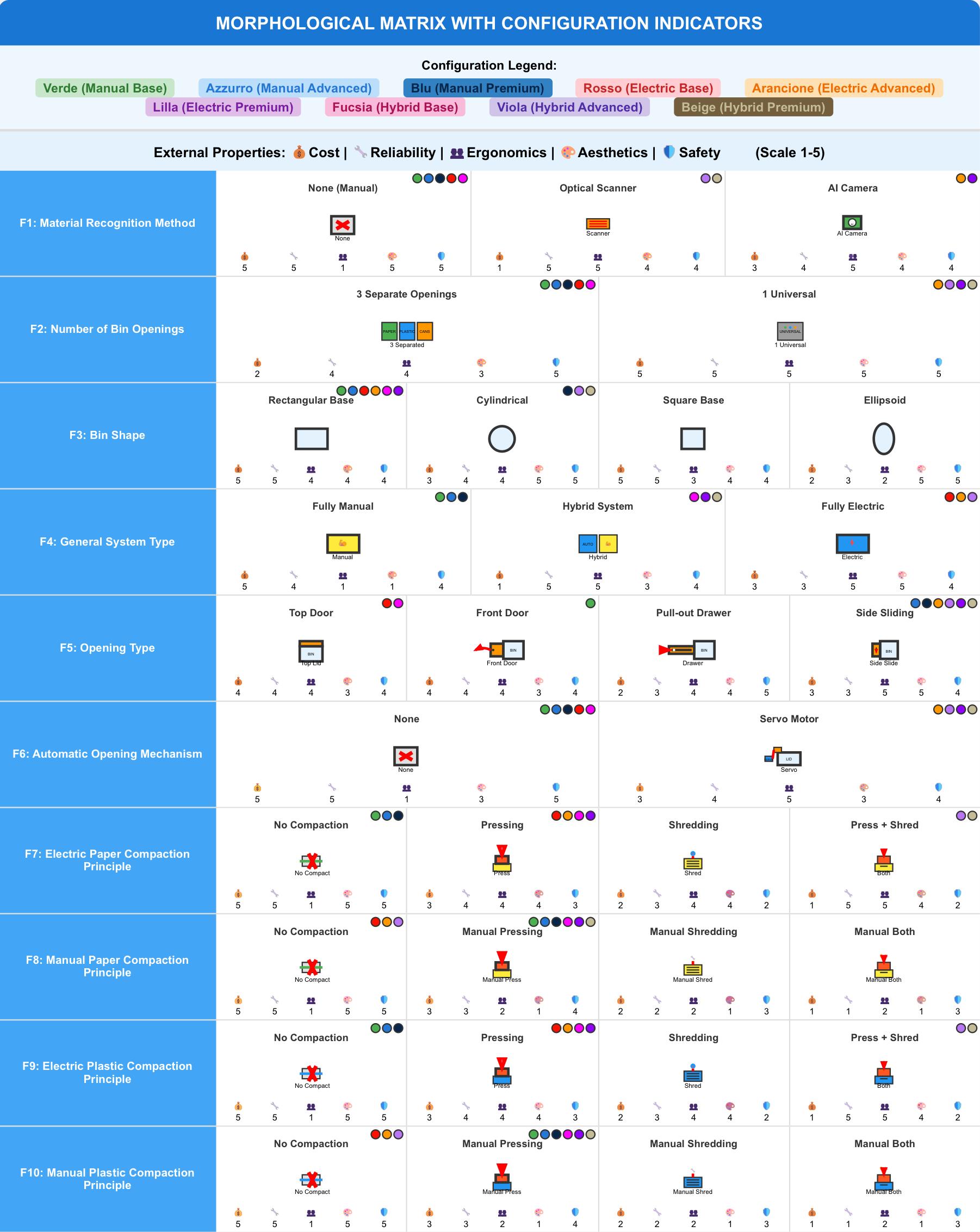
The early phase translated user needs and market gaps into a structured functional model. The goal was to understand how the product should work before choosing a specific solution. SFA, TFA and the Morphological Matrix were used to map the operating sequence, break down the main functions and compare different technical options.
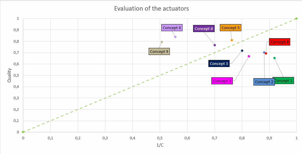
The final concept was selected from nine generated alternatives across different solution families. The decision was based on a quality/cost evaluation and Pareto/PDS reasoning, to support a more objective design decision.
The goal of this step was not to choose the most complex option, but to select the concept with the best balance between performance, feasibility and cost.
The chart shows the comparison that led to Concept 5 as the final design direction.
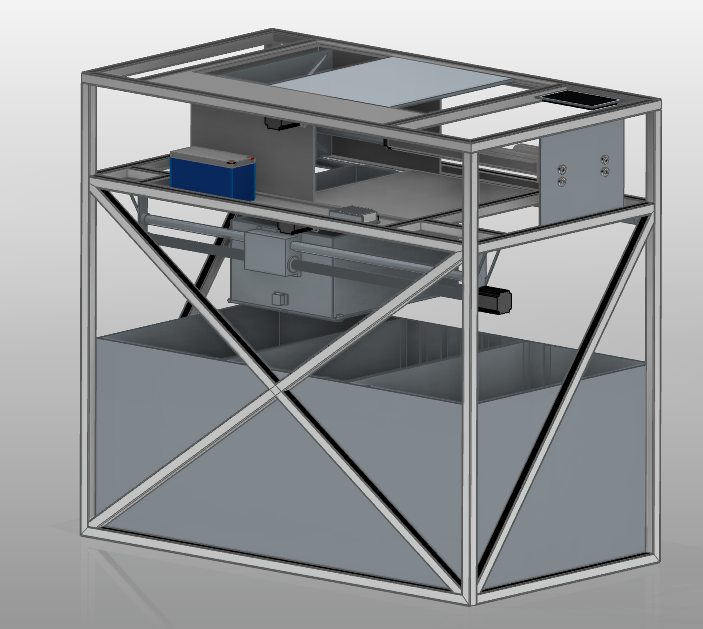
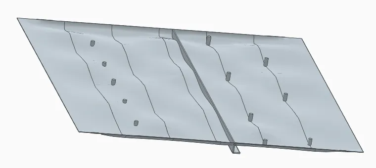
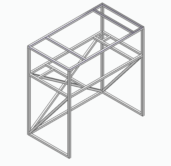
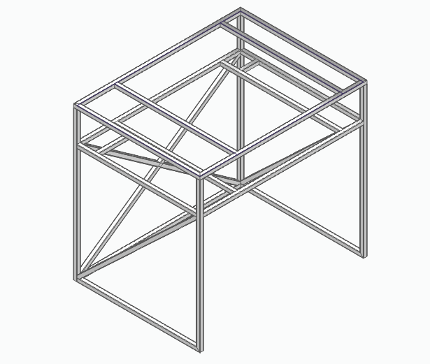
The CAD architecture was organized around load paths, accessibility and modularity.
After concept selection, the system was developed as a complete assembly,
including structural elements, moving parts, actuator interfaces, fastening points and removable containers.
The model was used to check the overall layout, component placement and interactions
between the main subsystems before moving to sizing and validation.
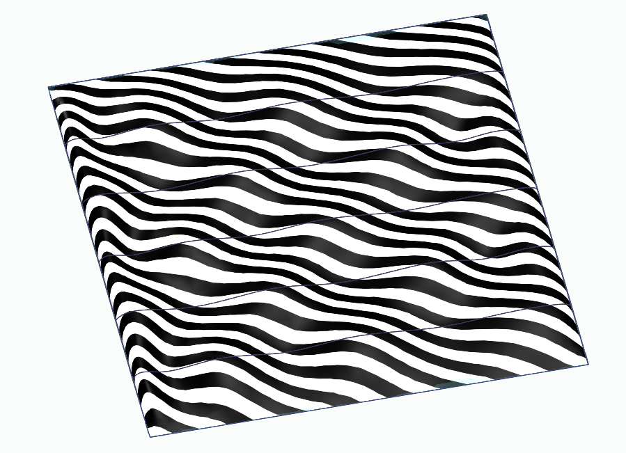
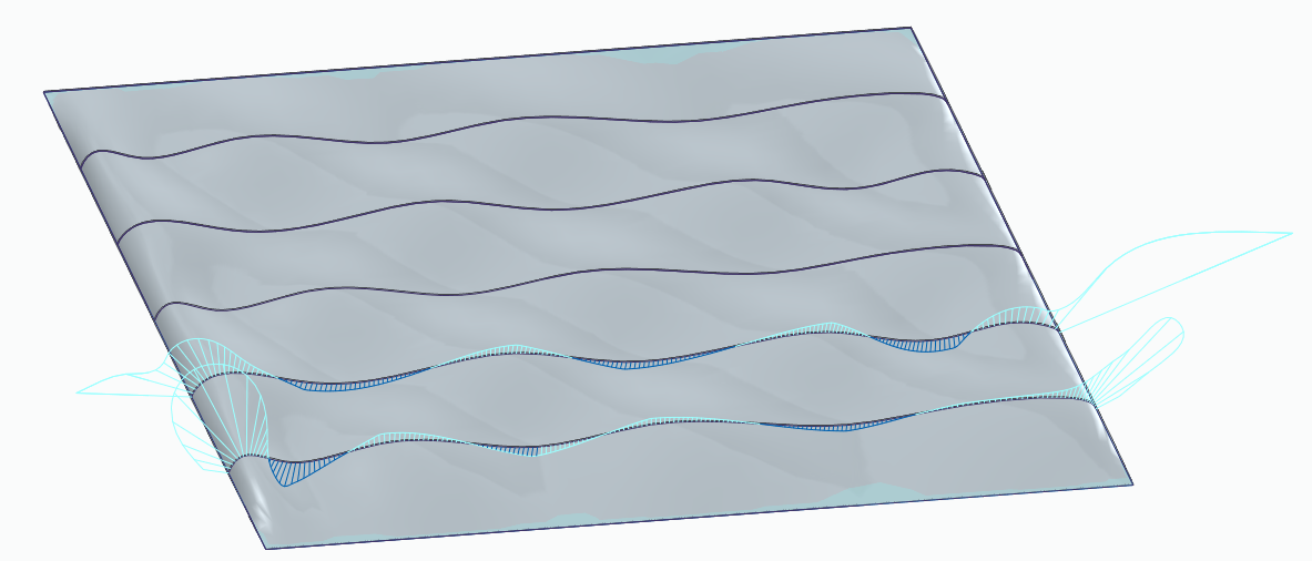
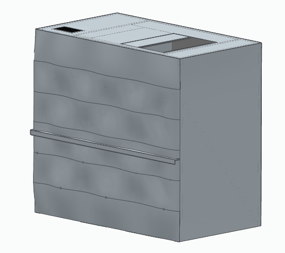
The external panel was designed using surface modelling, not just as a closing cover but as part of the product layout.
The work focused on shaping a clean front surface,
checking its continuity with zebra and porcupine analyses, and then adapting it to the final CAD assembly.
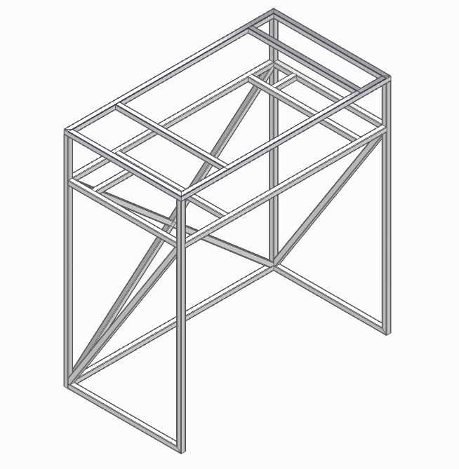
The frame was developed parametrically so that dimensions and interfaces could be adjusted without rebuilding the model from scratch. This made it easier to test different layouts while keeping the same structural logic.
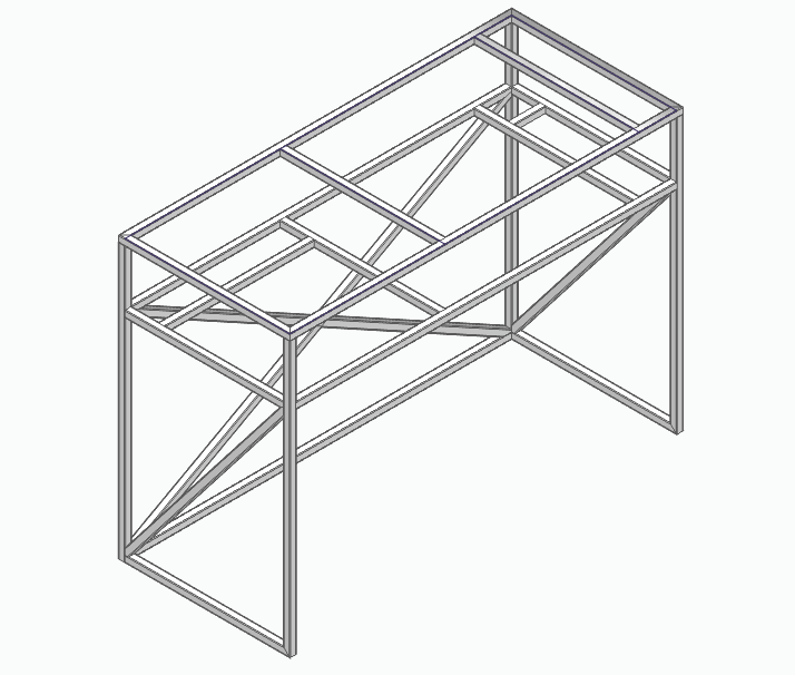
Critical subsystems were sized using a safety-margin approach
to verify their strength and stability under the expected loads and operating conditions.
The main checks included:
Can crushing was treated as a buckling-driven problem, then checked against experimental and commercial compaction data.
Stroke, force capacity, rod stability and positioning accuracy were sized to avoid buckling and preserve controlled motion.
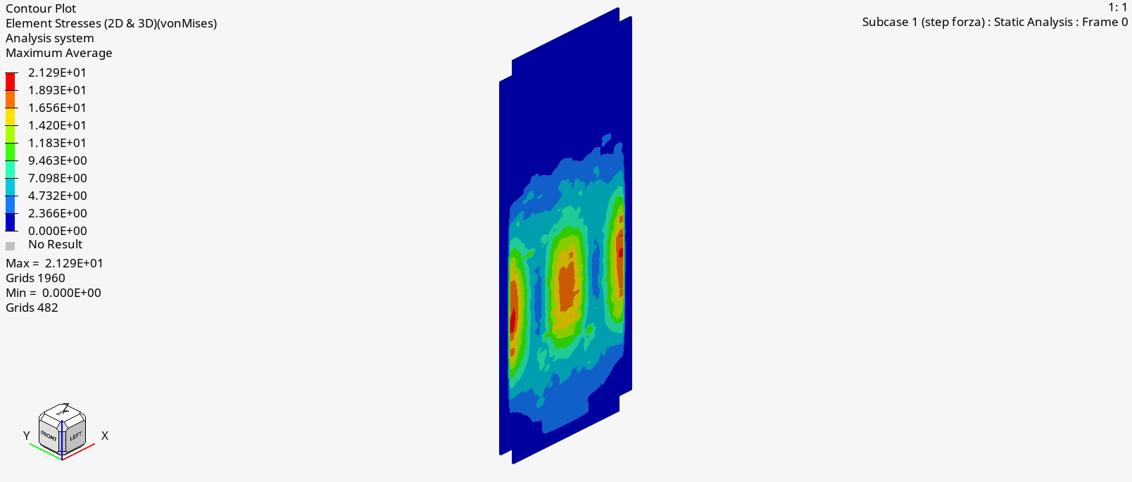
The plate was dimensioned for multi-format contact and reinforced to distribute eccentric loads toward the frame.
Compaction, displacement and storage volumes were coordinated to keep waste handling modular and accessible.
Posts and bracings were checked against compression and horizontal thrust while preserving a removable-container side.
The emergency battery and control unit were considered as part of the mechanical system integration, not as an afterthought.
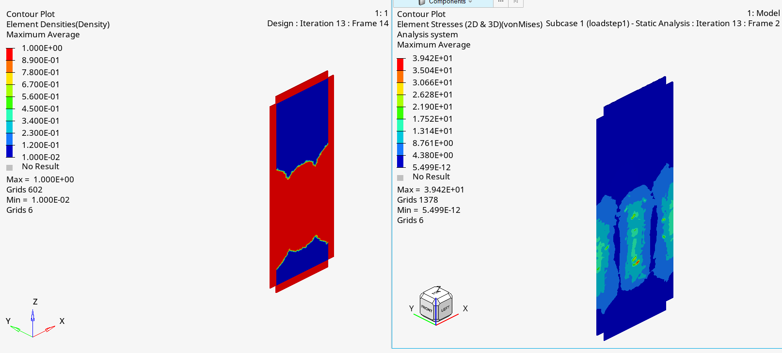
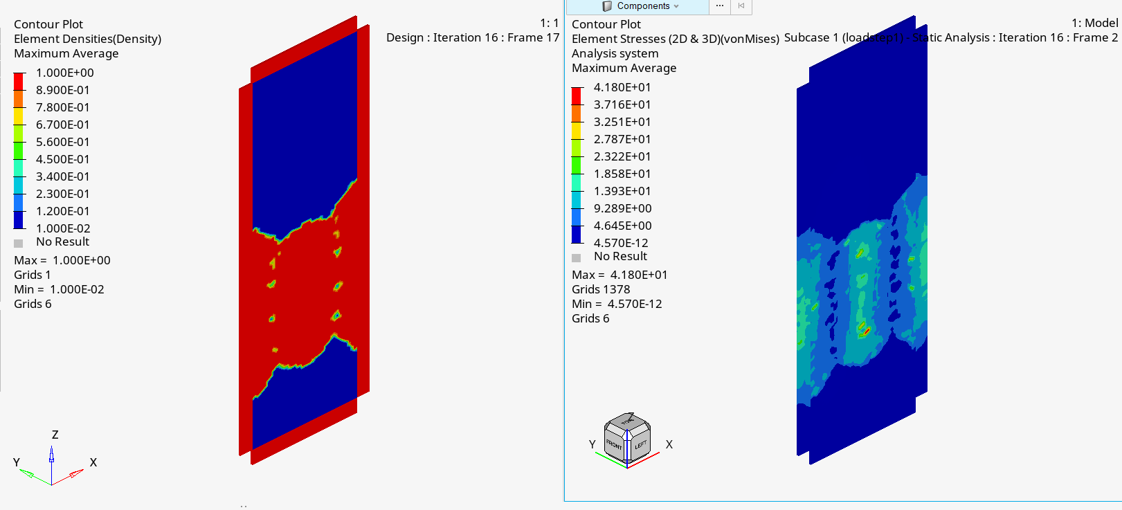
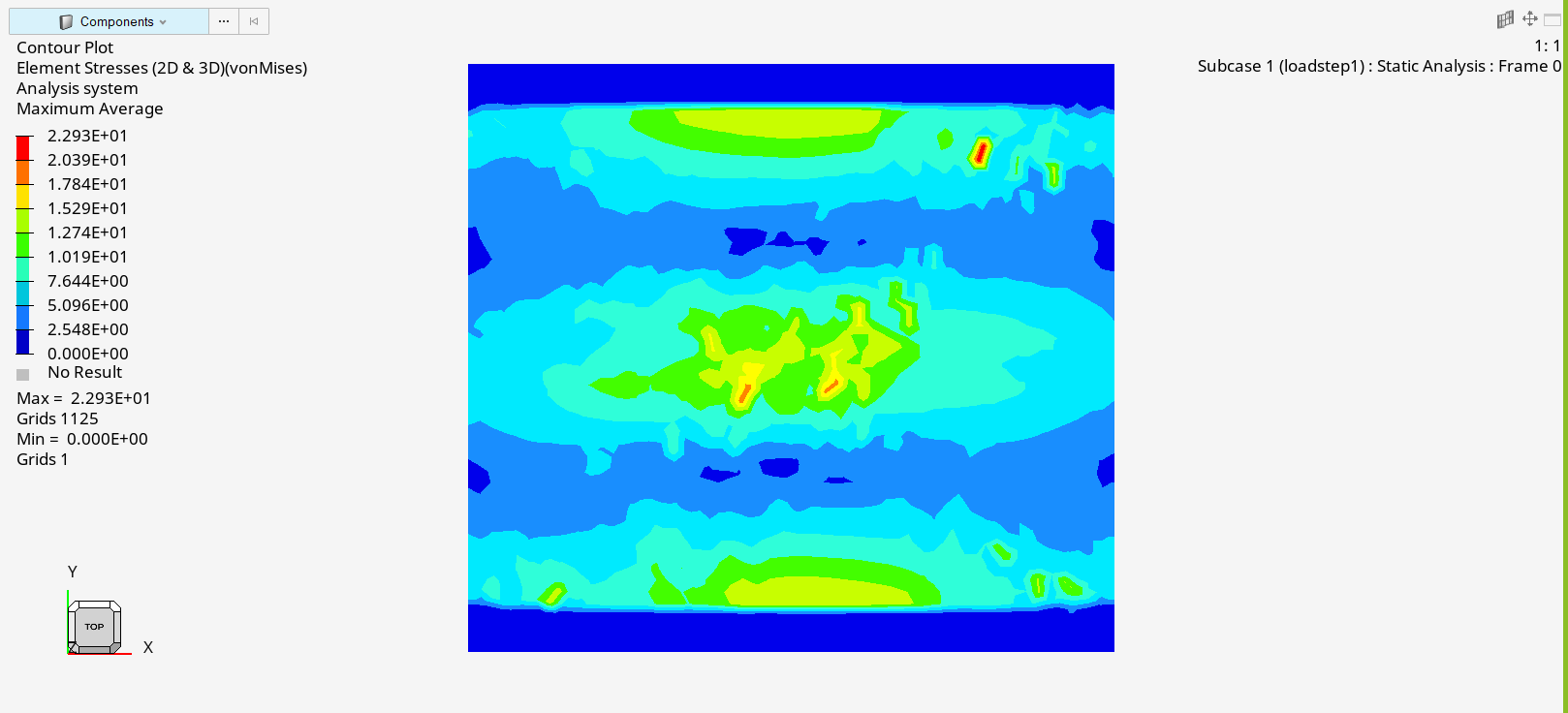
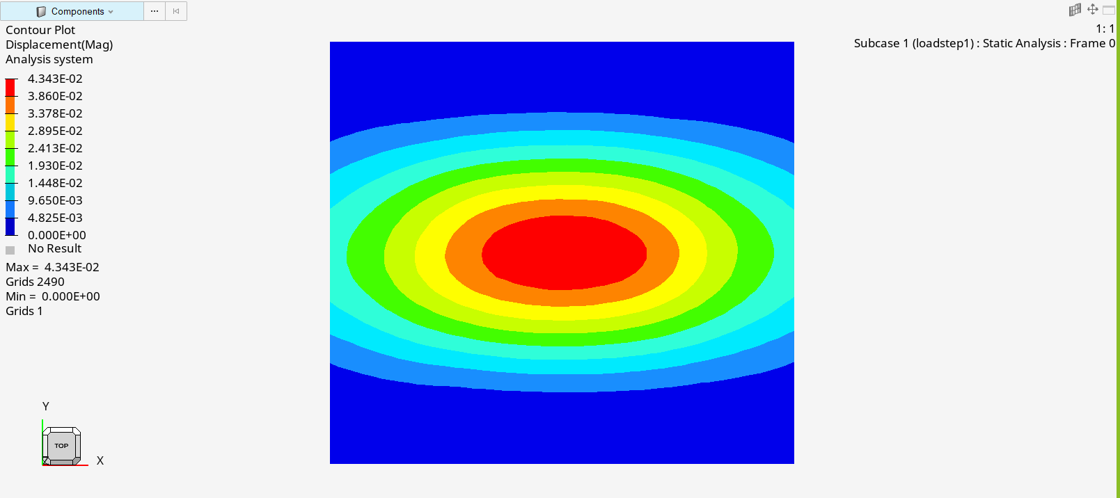
A FEM comparison was used to choose the material for the critical structural plate. Steel and aluminum were tested under the same load conditions. Aluminum reduced the weight, but showed higher displacement and a lower safety margin. For this reason, S235 steel was kept and the weight reduction was moved to the next step: topology optimization.
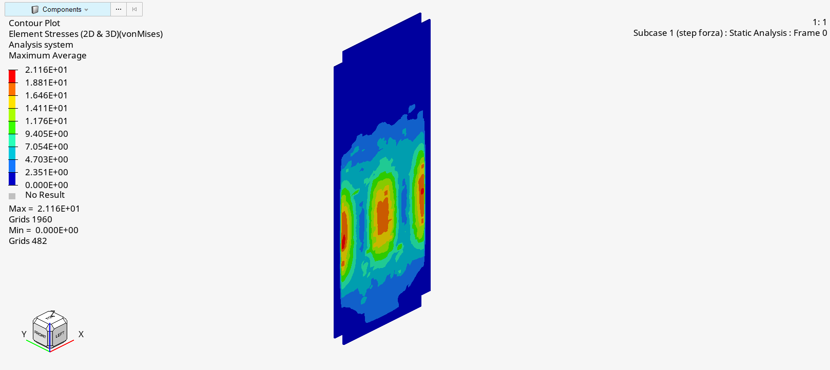
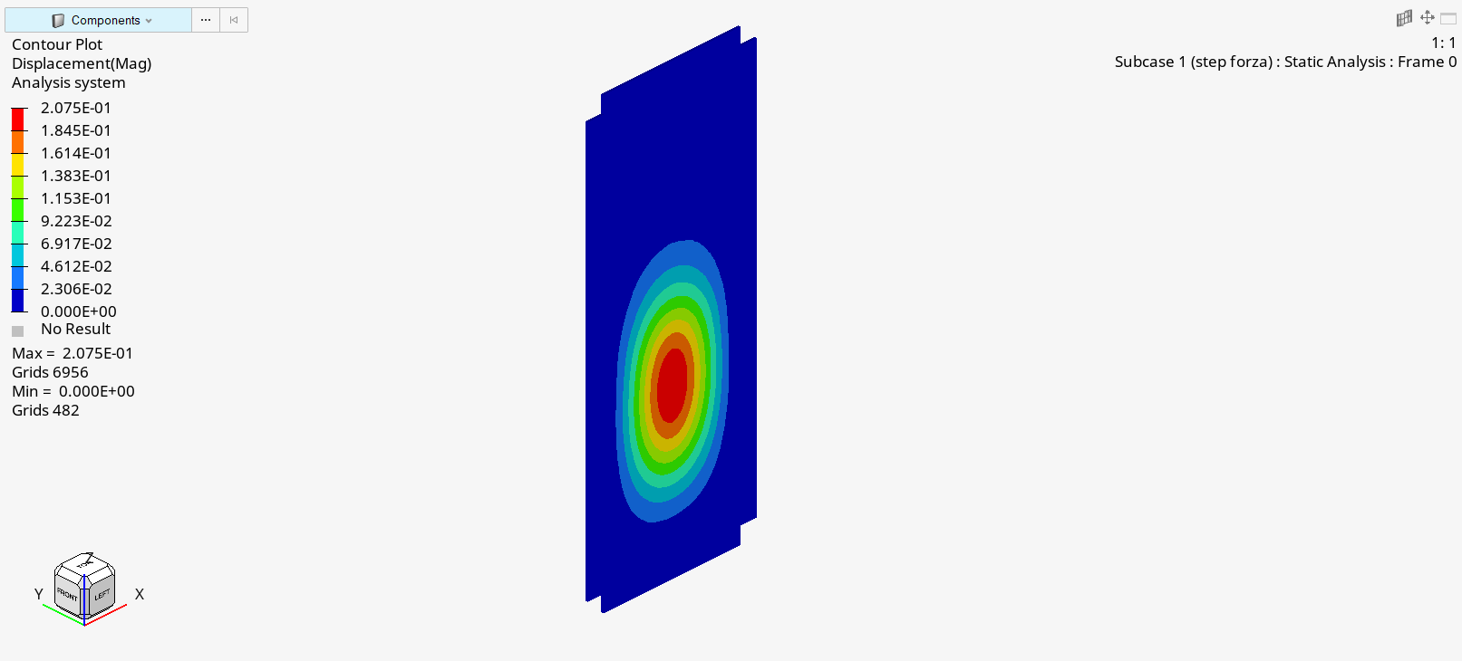
Lower weight, but higher displacement and insufficient safety margin for this component.
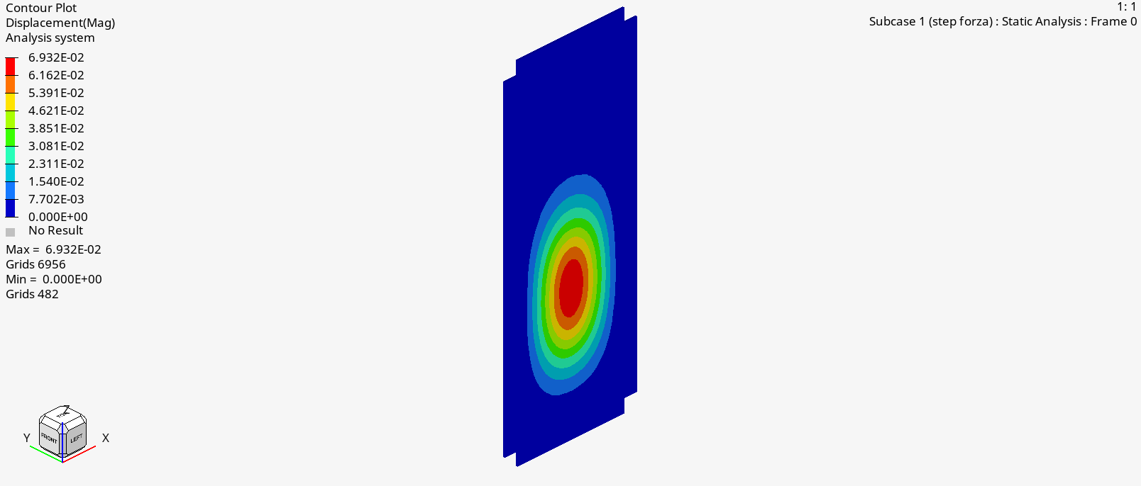
Higher safety margin and lower displacement under the same load case.
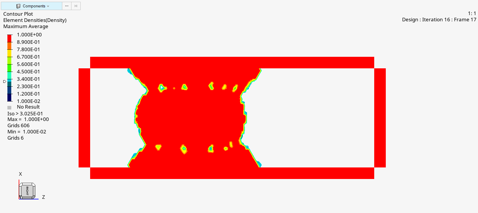
Topology optimization was used to understand where material could be removed from the steel plate without compromising its structural behaviour. The optimization result was not used directly as a final part. It was converted into a reference shape, rebuilt as a cleaner CAD geometry and then checked again with FEM.