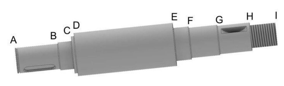
Cutting 90 mm bar stock into 530 mm blanks for the 192-shaft lot.
Back to projects
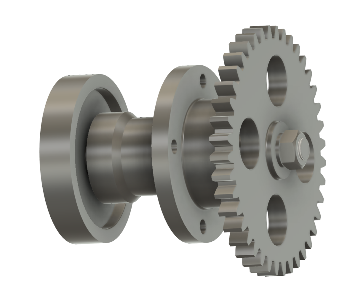
Manufacturing Process Design for a Geared Transmission
This project developed the manufacturing strategy for a geared mechanical transmission, linking functional analysis, shaft sizing, material selection and tolerance definition to production-cycle planning for the cast frame, machined shaft and hot-stamped gear.
01
System Function And Component Strategy
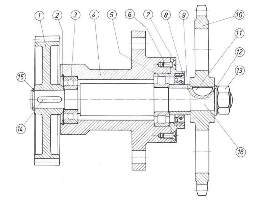
The early design phase translated the transmission assembly into a manufacturing strategy for each main component. The shaft was assigned to machining from commercial bar stock, the frame to casting, and the gear to hot stamping, while catalogue components such as bearings, seals, keys and Seeger rings were selected around the required interfaces.
Transmission ratio2.67
Input power117.78 kW
Batch size192 pieces
02
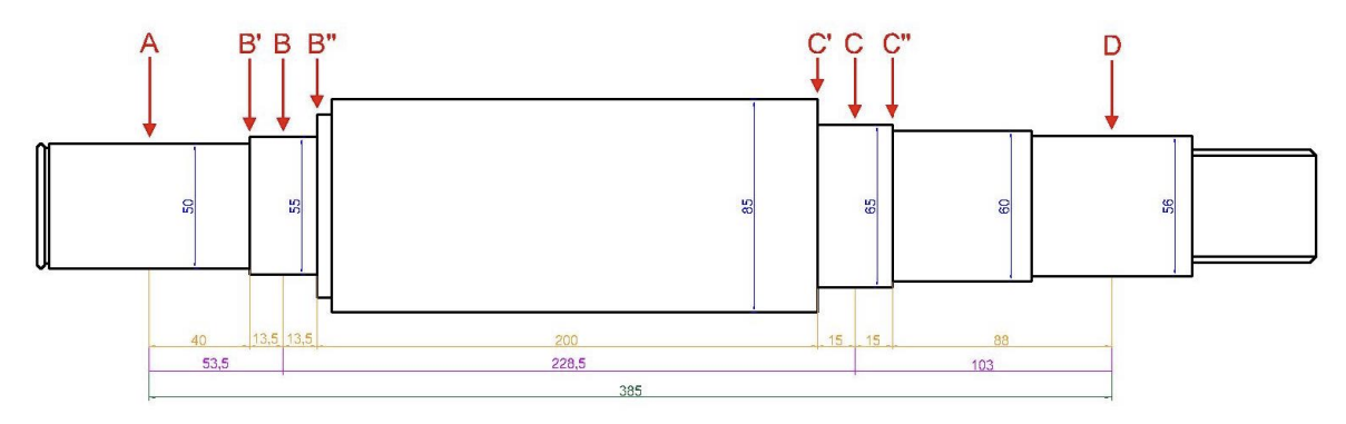
Shaft Sizing And Critical Section Analysis
The shaft was evaluated under combined bending and torsion. Bearing reactions and bending moments were calculated in the vertical and horizontal planes, then the critical sections were compared by accounting for shoulders, keyways and stress-concentration effects. Although section C carried a high bending moment, section B became critical due to local stress concentration, leading to the final verified shaft diameter.
- Speed: 562 rpm.
- Torque: 2001 Nm.
- Critical section: B.
- Fatigue safety factor: 2.17.
- Selected material: 40NiCrMo7 steel.
03
Functional Surfaces, Fits And Tolerances
Functional surfaces were identified before defining the manufacturing cycles. Bearing seats, gear-shaft interfaces, keyways, seal seats and threaded connections required tighter tolerances and surface finish than non-functional areas. This analysis drove the choice of machining allowances and finishing operations after casting or rough machining.
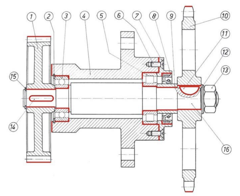
Controlled Features
- Bearing seats and coaxial cylindrical surfaces.
- Gear-shaft fit and keyseat positioning.
- Seal seat and threaded shaft end.
- Planarity, cylindricity, coaxiality and roughness requirements.
- ISO fit logic such as H7/n6, H6/n5 and N7/p6 where required.
04
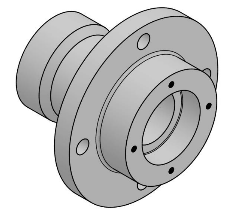
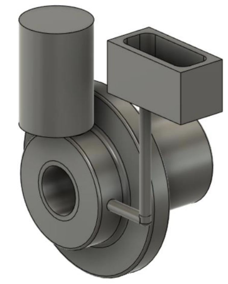
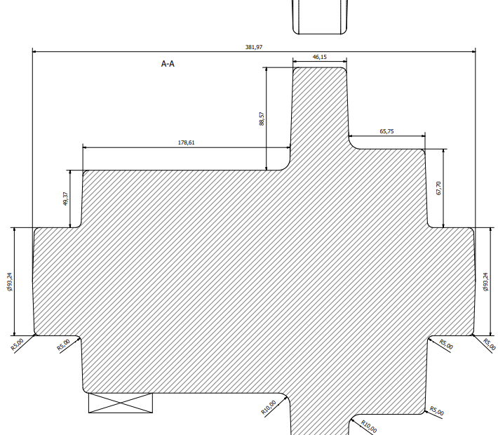
Casting Process For The Frame
The FE G 520 steel frame was treated as a casting problem rather than a direct copy of the finished part. Small holes were removed from the cast geometry, machining allowances were added where functional surfaces required later finishing, and the geometry was adapted for model extraction and directional solidification.
Temporary sand moulding
Machining allowances
Parting plane
Chills and riser
Core and gating
Metallostatic checks
The casting plan included temporary sand moulding for the limited batch, parting plane selection through the symmetry axis, thermal modulus reasoning, chills for directional solidification, an insulated riser dimensioned with Caine's method, a core for the internal passage, a pressurized gating system and metallostatic force checks.
05
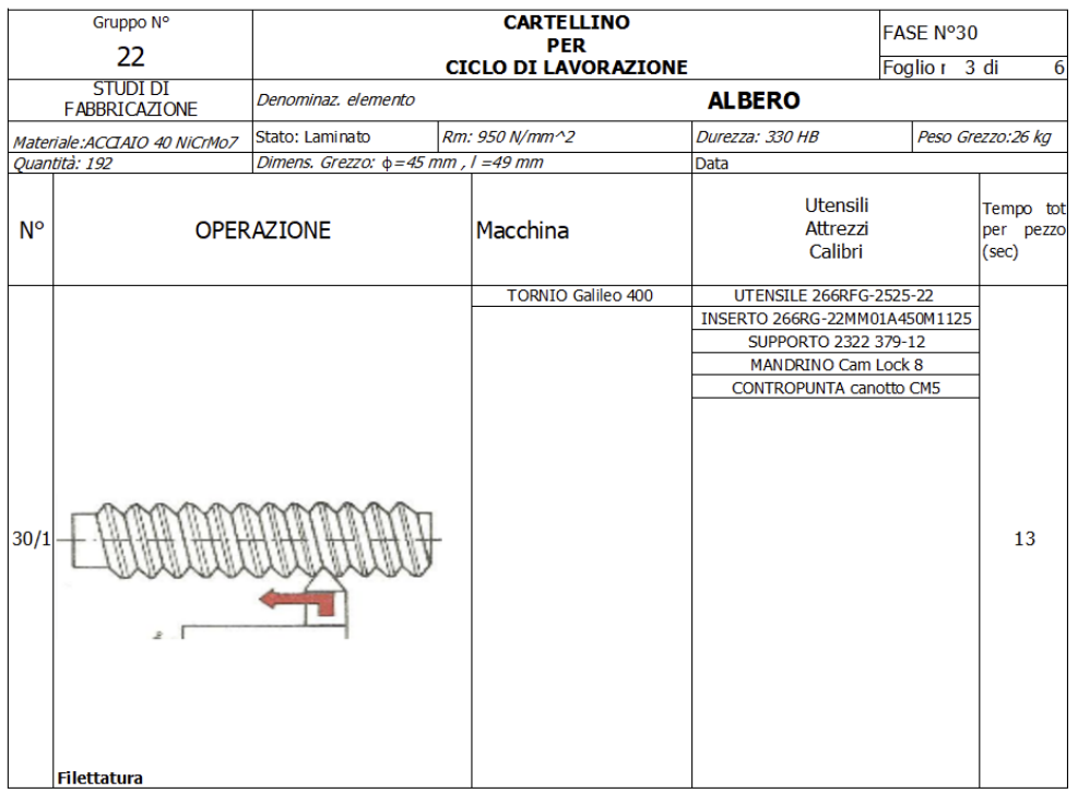
Machining Cycle For The Shaft
The shaft production cycle was planned from 90 mm commercial 40NiCrMo7 bar stock. The process included cutting, rough turning, finishing, threading, grooving, facing and milling of the two keyseats. Cutting parameters, insert choice, spindle speed, power demand and insert consumption were estimated to verify that the selected machines and tools were suitable for the production lot.
Commercial bar
Cutting
Rough turning
Finishing
Threading
Seeger groove
Facing
Keyseat milling
06
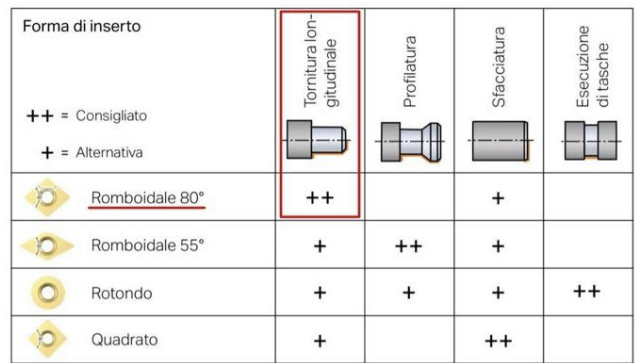
Tooling And Machine Selection
Tooling and machine selection was linked to the calculated cutting power, spindle speed and process accuracy. Roughing operations drove the maximum power requirement, while finishing and keyseat milling were selected to satisfy tolerance and surface-quality requirements on functional areas.
Roughing, finishing, threading, grooving and facing with verified workholding and power demand.
Rounded keyseat and Woodruff keyseat produced after turned surfaces were established.
Insert selection based on operation type, material class, cutting parameters and insert life.
07
Gear Stamping Process
The gear was planned as a hot-stamped component. The process definition included the flash plane, flash channel, machining allowances, draft angles, fillets, material volume and required forming force. Holes and final functional surfaces were planned as post-processing operations.
- Material: C45 steel.
- Flash and draft logic defined before final machining.
- Through holes planned as later machining operations.
- Final machining and heat treatment considered in the route.
08
Production And Cost Reasoning
The project also included preliminary production-cost reasoning for the batch size. Costs were estimated from material consumption, models, tools, inserts and selected machines, connecting the technical process plan to manufacturing feasibility.
192 components used to reason about casting model cost and machining setup logic.
Commercial shaft bars, cast frame blank and hot-stamped gear blank estimated from geometry and allowances.
Machine time, insert consumption and tooling choices connected to production cost.